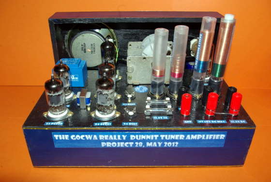
The Really Dunnit 13.8V Tube Tuner Amplifier
By G0CWA
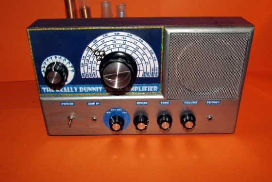


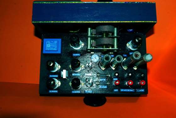
Hi I’ve “REALLY DUNNIT” this time with this, my latest radio project. The set is a combined LW, MW and SW regen receiver with combined audio amplifier. The set is designed to run off a standard radio/cb 13.8V power supply for ease of use, no nasty high voltages yet. Possibly in one of my later projects.
The set will run on higher HT voltages, but, at HT voltages of greater than about 28V you may need to play slightly with the valve biasing to get the best performance. In saying that, the sets performance is much better with an HT voltage of 21V.
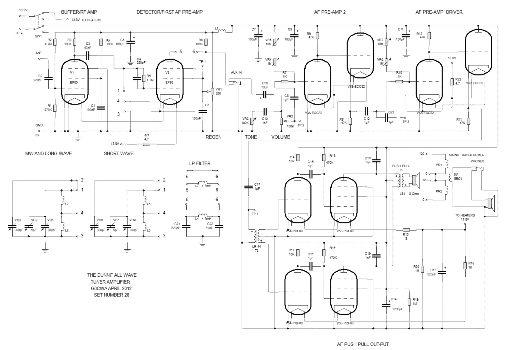
The Circuit Description
The set can be split into sections which are discussed below and identified on the schematic diagram included.
RF circuit
These stages get their HT supply via L1 an RF choke coil consisting of around 20 turns on a ferrite ring to reduce any RF feedback to the power rails
The input buffer amplifier.
This is a standard RF pentode based unity gain amplifier using an EF80 RF pentode. It is included for two main reasons these being isolation of the input and providing a constant impedance to the tank circuit. Both of these help to maintain both the Q and loading of the tuned circuit with the added advantages of helping to prevent re-radiation from the detector and preserve tuning calibration with different antenna systems.
The tuning Tank circuit
This is a “standard” parallel tuned circuit with a tap on the coil for the regenerative feedback. The actual tap position is a select on test (SOT) position for best performance, around 20% up from ground is a good starting point. The tuning range will depend on the capacitor used and inductance value used. An “estimate” of the actual inductance required can be calculated using my mystery coil calculator. Please note this calculation will tend to give an artificially high maximum resonant frequency due to no allowance being made for loading of the resonant circuit. Less turns will probably be needed than are actually calculated; this is again unfortunately another SOT value.
Various coil and capacitor combinations can be used for different “bands”, either by being switched in or by different plug-in coils.
With my version of the set although the coils were switched I descided to use sockets so I could easily “play” with different coil types using the receiver. it is actually probably a good idea to include a spare one just for this purpose.
Detector / First AF Pre-amplifier
This is again a standard RF Pentode, EF80, based regenerative detector with its output going through a low pass filter to the aux in jack socket. I used option 2 a single choke coil.
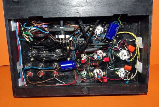
AF circuit
The AF amplifier is fed from either the tuner or external input selected via a switched jack socket. This is based on my “Dunnit” amplifier.
AF amplifier
The two pre-amplifiers use an ECC82 each (although an ECC81, ECC83, ECC88 or equivalents may be used) I used ECC82’s as I had some. the preset resistors being used to set the no signal bias current. Adjust these to get between 4.5 and 5.5 volts on the anode. If this can’t be done start by adding fixed resistors in series with the variable combination and try again. The reason for including the two resistors is for coarse (10M) and fine adjustment (1M).
The output from the pre-amplifier stages is fed through an Eagle brand LR44 transformer. The output from this drives the two “fairly standard triode-pentode” push-pull stages, again notice the positive bias on the grids. Each of these stages (using a PCF80 or PCF802) feed a 120-120 to 6V power transformer used as an output transformer, giving around 3.2K? input impedance for an 8? output impedance ideal for the PCF80.
See my article on Valve Audio Transformers, An Alternative Approach.
The circuit, as I have drawn it allows the use of either 13.8V or higher HT voltages. With increased performance with higher HT (I tried between 12 and 60V). The valve biasing may need to tweaked above28V. For use with 13.8V HT just feed the heaters and HT from the same source.
Basic Valve Specifications
V1 & V2 EF80 HIGH SLOPE RF PENTODE 6.3V 300ma FILAMENTS
V3 & V4 ECC82 AF DOUBLE TRIODE 6.3V 300ma FILAMENTS WHEN WIRED IN Parallel on each valve.
V5 & V6 PCF80 AF TRIODE PENTODE 9V 300ma
Dropper Resistor Calculations
Use Ohms law, the PCF80s each valve
You need to drop 13.8 – 9 or 4.8 volts at 0.3A
Using V = I x R
Required resistance = 4.8 / 0.3 or 16 ohms
Power dissipation is P = I x V
Power rating is 0.3 x 4.8 = 1.5W minimum
Use 18 Ohms at 3 Watts minimum to slightly under-run the valve filaments
The dropper resistors for a 13.8V supply are:
The EF80s in series 4.7? @ 3W (6.3V @ 300ma each)
The ECC82s in series 4.7? @ 3W (6.3V @ 300ma each with the separate internal filaments in parallel)
The PCF80’s separately 18? @ 3W per valve
Please Note
As with the Dunnit amplifier take care in choosing your loudspeaker; you need to pick an efficient one not just any old speaker you have lying around. The one I found gave me the best result was a plastic coned 8cm one rated at 8 ohms 12W this was closely followed by a standard car speaker, you will have to play here for best results, but definitely no miniature transistor ones. This is not a problem at higher HT voltages with the corresponding higher output drive levels.
At low HT voltages below 18V don’t expect deafening volume, high receiver sensitivity or Hi-Fi quality. The output and sensitivity are however sufficient for normal use.