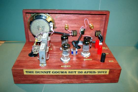
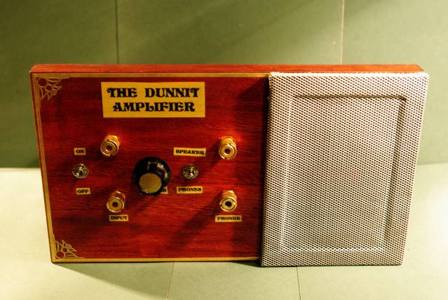
The Dunnit 12V Tube Amplifier
By G0CWA


Hi I am here again with my latest project the DUNNIT AMPLIFIER, Not another amplifier you say, yes but one that works on 12V HT using commonly available ex TV valves as the output ones that until now have been generally ignored for 12V use. The name was arrived at by friends saying it can’t be done with standard valves well I DUNNIT (done it) !!!!!
The technical bit
The amplifier is a fairly common configuration a pre-amp/driver and push pull output stage but the valves are being used in a starved configuration. This means the standard design charts do not apply as explained in the excellent article Triodes at Low voltages by Merlin Blencowe on Google. The main effect on the amplifier stages is grid current cannot be considered negligible as with higher HT voltages so they need to be positively biased in a controlled manner, hence the use of pull up resistors to provide a small bias current.
The major advantage of this configuration is unusually high gain, but with exceptionally high output impedance. Because of this a cathode follower is used, preserving the gain whilst matching impedances.
This is my understanding of the circuit operation as explained by Merlin Blencowe, I may be wrong.
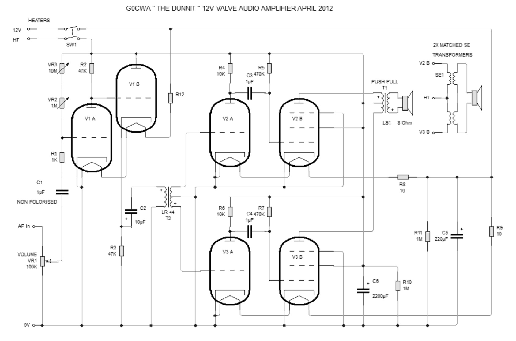
Circuit Description
The pre-amplifier uses an ECC82 (although an ECC81, ECC83, ECC88 or equivalents may be used). I used an ECC82 as I had one. the preset resistors VR1 and VR2 being used to set the no signal bias current adjust these to get between 4.5 and 5.5 volts on the anode if this can’t be done start by adding fixed resistors in series with the variable combination and try again. The reason for including the two resistors is for coarse (10M) and fine adjustment (1M).
The output from the pre-amplifier stage is fed through an Eagle brand LR44 transformer, the use of a proper valve transformer should improve the amplifiers performance, use what you have. The output from this drives the two “fairly standard triode-pentode” push pull stages, again notice the positive bias on the grids.
Each of these stages (using a PCF80 or PCF802) feed one of three combinations:
An Eagle Brand LT 700 transformer although this worked it was not very efficient and should be the last choice because of this.
A standard pentode valve push pull output transformer I didn’t have one so I used the final option
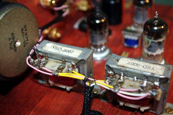
My option was to use two single ended transformers connected together as shown in the circuit diagram, take care about the phase relationship between the windings otherwise signals will cancel out. There are two major advantages of using two transformers; both the speaker impedances add together to give 6 ohms rather than 3 and cost. It is generally cheaper to get two MATCHED single ended transformers than a push pull one. At present on E-bay £5 compared to £20 or higher.
The circuit as I have drawn it allows the use of either 12V or higher HT voltages. With increased performance with higher HT (I tried between 12 and 60V the valve biasing did not need to be reset. For use with 12V HT just feed the heaters and HT from the same source.
Please Note
R 12 is replaced by a link wire for 12V operation
R10, R11 and R12 need to be changed to a suitable value if a 12V heater supply is not used.
PCF80 9V 300ma Heater
ECC82 12V 150ma Heater (Used in series)
Use Ohms law to calculate the required resistance and then use the next highest preferred value to act as the dropper resistor see below for 12v heater supply.
You need to drop 12 – 9 or 3 volts at 0.3A
Using V = I x R
Required resistance = 3 / 0.3 or 10 ohms
Power dissipation is P = I x V
Power rating is 0.3 x 3 = 1W minimum
Dropper resistor is 10 or 12 ohms at 1W minimum I would use 3 watts always err on the high side for both values to prevent the magic smoke that makes a component work from escaping!
If the amplifiers gain is not high enough for your uses graft another ECC82 stage in the front of the amplifier, it does work, I’ve done it, but you may get more gain than you need resulting in clipping and subsequent distortion of the audio. If doing this I would suggest a second “volume control” in the form of a preset between stages to throttle the signal back until any distortion is reduced to acceptable levels.
Additional Notes
Take care in choosing your loudspeaker; you need to pick an efficient one not just any old speaker you have lying around. The one I found gave me the best result was a plastic coned 8cm one rated at 8 ohms 12W this was closely followed by a standard car speaker, you will have to play here for best results, but definitely no miniature transistor ones. This is not a problem at higher HT voltages with the corresponding higher output drive levels.
In conclusion the amplifier works well on both regenerative and crystal sets, but, particularly at low HT voltages below 18V don’t expect either deafening volume or Hi-Fi quality the volume is however sufficient for comfortable listening.
Thanks again Dave for your help in getting me to think outside of the box to arrive at the final design
Enjoy your building 73 for now Nick
Corrections and additions
The heater dropper resistors should read R9, R10 and R12 NOT R10, R11 and R12 as in the body of the text
The small modification to the amplifier circuit of adding two extra capacitors of around 1 to 10nF (SOT) across each of the two output transformers primaries has been found to significantly improve the tonal quality of the amplifier with a very small sacrifice in overall gain. This may well be a useful modification for you to do if you decide to build your own version.