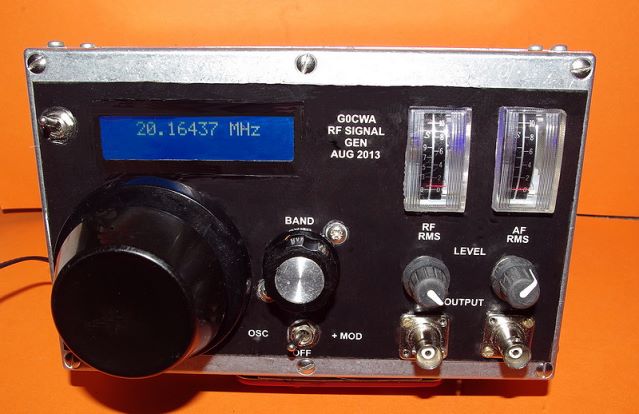
RF Signal Generator Project
By G0CWA – February 2014


A full write up is included as a downloadable PDF file
Hi welcome to my design for a simple (and cheap) RF signal generator with both AM and FM modulation. The version I built was to fill in the gaps not covered by my old commercial unit and also provide an item of test equipment in its own right. As built the frequency range mine covered was 16KHz to 54 MHz although with suitable coils it should work from as low as 5KHz to over 100MHz.
This frequency range was covered in 11 ranges the twelfth being left unused and can be used as a standby setting to in some measure maintain the temperature within the case and hence minimise thermal drift, or even a din socket (I would suggest on the back) for plug in extra coils/ranges.
I soon discovered that my first ever lesson in Amateur Radio, all those years ago, held true. THE AMOUNT OF SPACE REQUIRED IS PROPORTIONAL TO THE AMOUNT AVAILABLE SQUARED !
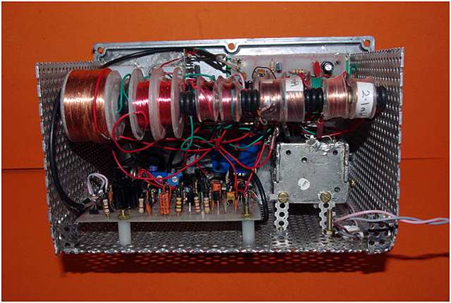
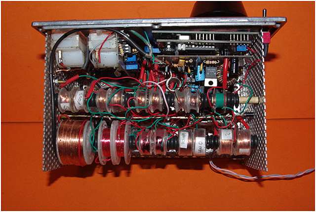
This law meant the case I had bought was too small and had to be enlarged as I am lazy and did not want to do any more major metal bashing, I achieved this as shown below by using longer metal bolts and a homemade case "extender".
As with all my project designs this is of a modular construction and you can build as many of the extras as you wish, I may well do some external plug on units later.
Please note calibrated dials can be used instead of the meters with, I would recommend, an external frequency meter and scope used for setting up.
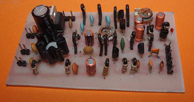
The main Board
The main board is the only one you have to build for the minimalist version as the regulator etc. is on this board.
The circuit is based on a modulated wideband colpitts oscillator. Unfortunately with such a simple approach the signal amplitude will vary with frequency particularly as to keep it simple and the price down I have not included any form of AGC.
The use of a class "A" power amplifier (2N3866 or similar) means the oscillator should be able to drive a 7dBm mixer directly (SBL-1 etc) on most ranges, a very useful feature.
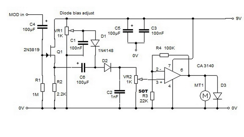
The modulation is achieved by the use of a phase shift oscillator controlling the supply voltage to the oscillator, crude but effective, this produces amplitude and slight frequency modulation, very useful.
Level meters
These are based on my RF mV meter at: http://makearadio.com/visitors/nick-rf-meter.php and are intended as indicators only, for absolute readings they will need to be calibrated.
Frequency meter preamp
This is based on a design I found on the net, unfortunately I can't find the URL again I was lucky first time round. It is designed to fit as a piggy back board on the frequency meter module I used that I obtained from E-Bay from “jpl995” and was listed as “FREQUENCY COUNTER 1HZ-80MHZ WITH 1HZ RESOLUTION”
Before anybody asks I opted for an analogue approach rather than DDS ( dirty digital synthesis ) as it is easier for the average person to build at home and does not involve the use of a pic etc.
Hope you find this a useful design 73 for now de Nick G0CWA
Any comments will be gratefully received and as usual I can be contacted by e-mail or via The RadioBoard and QRZ forums as G0CWA. I cannot guarantee to see your questions if posted elsewhere.
REMEMBER TO CHECK THE PCB TRACK LAYOUTS AND MIRROR THEM IF NEEDED. I HAVE PRESENTED THEM AS “X-RAY” VIEWS OF THE FINAL BOARD !!!!
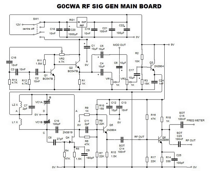
G0CWA RF Signal Generator Main Schematic (Larger View)
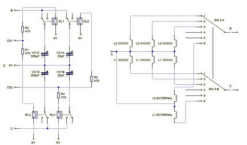
G0CWA RF Signal Generator Coil Switch (Larger View)
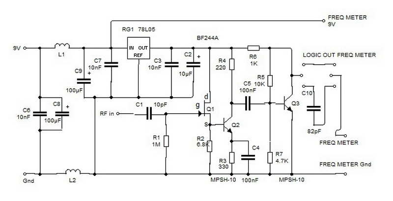
Frequency Meter Buffer (Larger View)