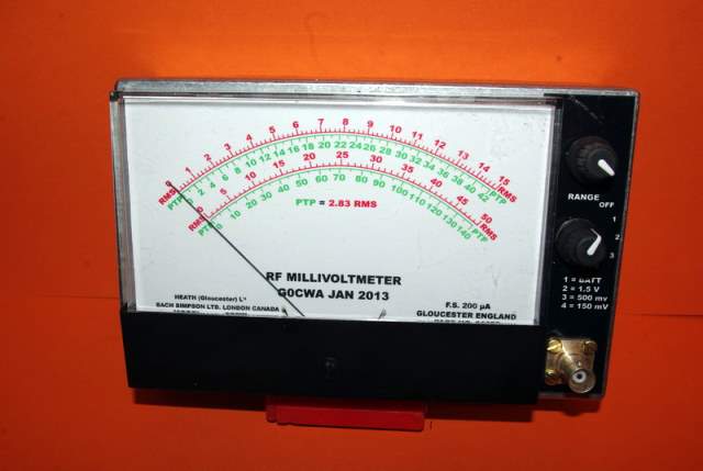
G0CWA RF Millivoltmeter


Hi welcome to my design for an RF mV meter.
The meter is not intended as an absolute instrument as no major attempt is made to compensate for the operating characteristics of the devices used, but, more as a cheap easily made RF indicator (In saying that on the two higher ranges an accuracy of around 10-15% was obtained at the higher voltage levels. The lower the voltage being measured the lower the accuracy (particularly below 200mV).
Despite these drawbacks in measurement accuracy I have still found it a very useful piece of equipment when either peaking a signal level or checking for gain in a particular circuit.
The unit is based on a combination of two already existing designs by: Rodney Byne and Jim Tregellas VK5JST
I was impressed by Rodney Bynes approach to the measuring part of the circuit and have virtually “cloned” it for my front end, the “Range select” part of the circuit is my main contribution, the meter amplifier is based on a design by Jim Tregellas.
Circuit Theory
I do not intend discussing this in detail as it is covered in fine detail on the pages listed above.
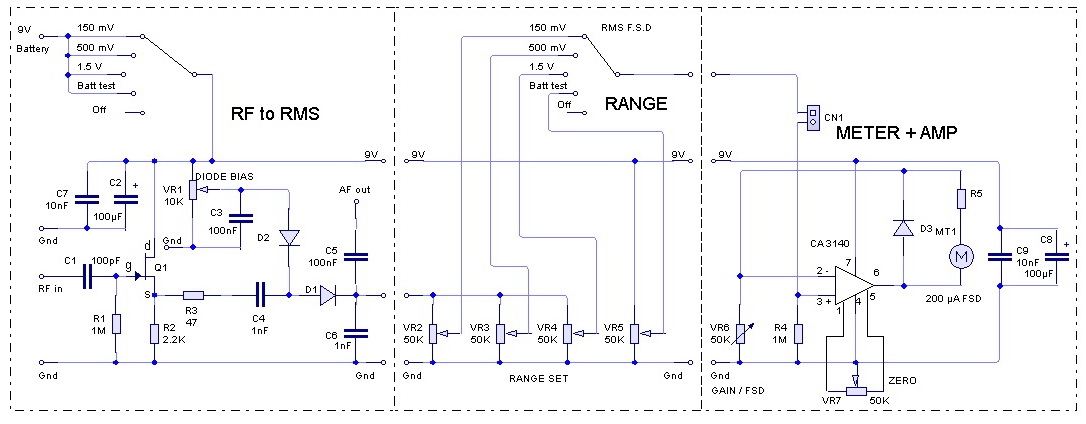
The input circuit is almost a complete clone of Rodney Bynes circuit with one difference the range selection is achieved by a set of adjustable attenuators to not only convert the measured peak voltages to RMS values but also “normalise” them to a common output level for each required full scale reading. I used matched 1N5711 Schottky diodes throughout, although others may be suitable with a 2N3819 FET. In addition I also included an additional attenuator to enable checking of the battery voltage. Down to around 8V should be ok for operation.
The meter amplifier circuit gain is adjustable by trimmer VR6 and zero offset by VR7. The clever part of this circuit (based on the circuit by Jim Tregellas) is the incorporation of the meter movement in the amplifier feed-back loop, any meter from 50�A to 1mA FSD can be used but you may have to play with the value of VR6 increase its value for more sensitive meters, this can be achieved by including a series resistor with the trimmer. A front panel zero offset control is also included allowing control of any zero errors.
To use the meter for exact readings the meter deflection would have to be calibrated against known RF mV levels and frequency of say an RF signal generator.
Set Up Procedure
The set up is relatively easy but should be followed in full to obtain the best accuracy possible.
Firstly set the pre-sets to the settings:
VR1 to VR5 - set to earthy end
VR6 set to maximum resistance
VR7 set to mid way
1 Connect a DVM to the junction of D1, C5 and C6 gradually increase the setting of VR1 until a very low voltage is measured on the DVM, the lower the better this has set the DC bias of the diodes to its optimum value.
The next steps refer to a meter with a scale of 0 – 15 and 0 – 5 for others choose an
appropriate FSD reading. Eg 100mV, 300mV and 1V
2 Apply a 150mv RMS rf signal to the input and adjust VR2 to give a maximum reading on its wiper.
3. Slowly adjust VR6 to give a deflection of 150 on the meter.
4 Disconnect the generator and adjust VR7 to give a zero reading.
5 Repeat steps 3&4 “fine” tuning the 0 and required FSD readings until happy.
6 Alter the switch to 500mV and the input to 500mV RMS and adjust VR3 to give a reading of 500 FSD on the meter.
7 Alter the switch to 1.5V and the input to 1.5V RMS and adjust VR4 to give a reading of 1.5V FSD on the meter.
8 Alter the switch to Battery and slowly increase VR5 to give a reading of 9 on the meter.
Finally check the FSD readings tweaking as needed.
The set-up process may seem a little repetitive but is needed to ensure the best accuracy.
If you require accurate readings the meter scales must now be calibrated against input voltage AND frequency. As presented the meter should be sufficiently accurate for use up to several hundred MHz, mine was up to at least 150MHz the maximum frequency of my signal generator.
Please note:
Due to the high input impedance the meter will not load the circuit under test and the ideal probe would be a X10, X1 oscilloscope probe allowing measurements of 150mV to 15V RMS FSD.
Specification
Measurements from around 100KHz to at least 150 MHz
Best accuracy on a sine wave
Ranges 150mV, 500mV 1.5V RMS (X1 probe)
Ranges 1.5V, 5V, 15V RMS (X10 probe)
Zero adjust Feature
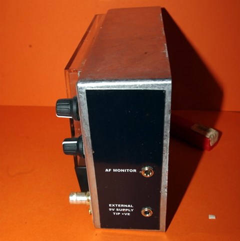
Audio monitoring of modulated AM signals on crystal earpiece.
Battery check.
N.B. This instrument is designed to measure VOLTAGE NOT POWER and excessive input levels will kill it. I hope you enjoy this design and find it a useful addition to your test equipment, happy measuring de Nick G0CWA