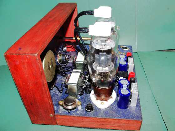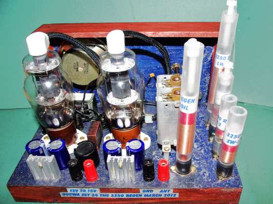
The G0CWA 325O All Band Regenerative Receiver
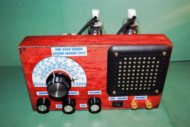


The main aim behind this radio was to build a valve radio that would power a loud speaker, not difficult you say, on 12volts HT, think again!
The name 3250 was chosen because the set uses 2 x 1625 valves one for the RF as a regenerative detector/audio pre amplifier the second being used as a power driver for, sorry for swearing, a single three legged fuse, sorry PNP power transistor. This was the only way to do it I’ve found at present with low HT and not using specialist very expensive valves e.g. the 12K5 .
Optional Bits
At first glance the circuit looks over complicated, in particular the power supply. This part of the radio is fully optional if you intend to run it solely on 12v. It is included for use at higher supply voltages for a higher HT to the valves the 7812’s are used solely to eliminate the tedious recalculation of the more common heater dropper resistor for the valves; one is used per valve to reduce the amount of heat-sink required
Please note the 7812’s only really start to function properly above 15v supply.
Please note only the value of R8 has to be changed on the reverse polarity protection part of the circuit to limit the relay current. This part of the circuit is again totally optional.
The next optional part is the bass boost circuit; under marginal conditions it can improve the low frequency response of the AF stages.
The final one is the inclusion of L9, this serves two purposes it can influence both the regen sensitivity and audio quality if in doubt leave it in, it won’t hurt.
The Radio proper!
Right now I’ve told you what not to build for the light version I’ll tell you about what you need to build to hear those radio stations. Those of you following my projects will recognise the front end it is basically my 1625 regen set with a minor modification.
This being to increase the value of C5 to 220pf to obtain reliable regeneration on my base band (MW) through the tuning range. This can be increased in value to increase regeneration levels by an additional select on test cap in the coil assembly C17. If regeneration is ok just leave it out and pin 7 on the coil din mount open circuit.
C15 is in series with the main tuning capacitor and serves to reduce the capacitance swing and hence the tuning range, most useful on the short wave bands. If it is not used short pins 1 and 2 on the coil assembly.
C16 is used to reduce the antenna coupling and hence tank coil loading to enhance the sets performance, in particular at higher frequencies. Unfortunately it is another SOT item and can be as low as 1pf up to pins 5 and six being shorted out for maximum coupling.
Please note the main tuning cap is controlled using a 10:1 reduction drive.
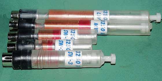
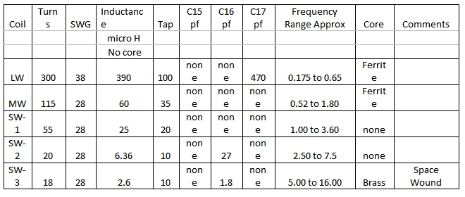
My coils were made in the same manner to my multiband crystal radio with ferrite cores etc and a brass core to reduce the inductance on the SW3 coil. The broad coil details are summarised below and should work for you but bear in mind the tapping point on the coil is a SOT position for best operation.
The sets overall performance can probably be improved by using larger diameter or even spider-web and basket weave coils, feel free to play. I was limited by size constraints to this diameter of coil. I would be interested to hear if you do play.
The final component worth mentioning is the output transformer of this stage I used a 100 v line matching transformer with a 4w output tapping, don’t be frightened to try other taps this just gave the best results on my set.
My Coil set is listed below, bear in mind you may have to play with values for best results but these are a good starting point.
Audio Stage
The audio stage started out as a clone of Sir Douglas Hall’s Pentonlector record player amplifier but had to be significantly modified for reliable operation at 12v HT.
The valve, V2 another 1625, acts as both an audio pre-amplifier and power driver for the transistor which cleverly supplies both the valves HT and audio power amplification. The major problem of this common collector configuration is thermal runaway destroying the transistor but as its maximum current rating is around 15A and it will only see around 200ma it should not even get warm so no heat-sink is needed.
The major difference from the original circuit is the transistor collector is tied to ground and not the cathode. This was a necessary modification due to the reduced HT supply. You should have no problems but if the valve does not give sufficient gain play with the value of R9 to get around 1.5-1.6V on the cathode, I had to.
The output is again fed through another 100v line matching transformer.
Final Thoughts
The set although working well up to 14MHz, I’ve not tried it higher. May be improved in several ways. I will leave it to you to play.
The ways I can think of:
Increasing the valve HT (you may even be able to omit TR1)
Winding the Coils in a different manner (Rook or Basket weave)
Winding the coils on larger size formers
Using Litz or larger diameter wires.
Including a small pll tuning cap across C3 for fine tuning of say 5pF
Enjoy playing and as usual I can be contacted at n.strong@hotmail.co.uk with any comments or questions, if I can help I will.
Remember it is only a hobby enjoy yourself.
Finally thanks to both Dave and Pete Friedrichs for your help and suggestions along the sometimes painful design stage!!
73 for now Nick Strong G0CWA
Listen to a short demo WMA audio file.