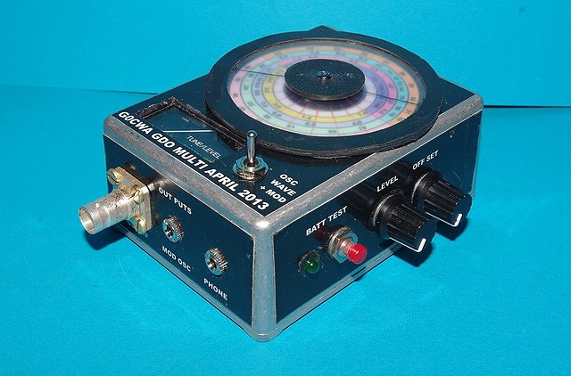
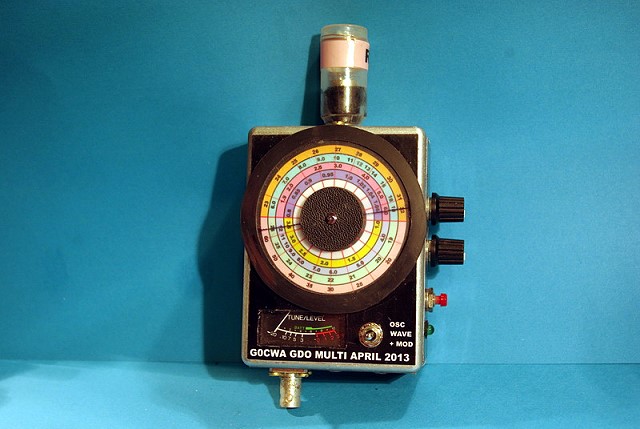
Grid Dip Meter Design
By G0CWA May 2013


This, my next offering of test equipment is an exceptionally useful item of test equipment with many uses, some are listed below. To coin a phrase given to me by one of my friends a GDO is the radio test equipment equivalent of a Swiss army pen-knife, thanks Pete. I have taken it several stages further than normal for a GDO and included a few more features. Although I have only made coils for use up to 70 MHz from 800 KHz by making additional coils the range can be increased to give from around 200 KHz to over 100 MHz with ease. I have owned a GDO for over 30 years and it has proven its worth many times over. I actually wanted to cover a larger low frequency range than my commercial unit would allow so decided to make another to “fill in the gaps”
The GDO uses are legion, amongst them are:
1. Measuring approximate resonant frequencies of items (antennas, traps, and tuned circuits).
2. Rough frequency and harmonic measurements
3. AM signal monitor receiver.
4. Simple RF signal generator including AM modulation if required.
5. Crystal Testing.
6. Use as a BFO for SSB and CW reception
7. Measurement of unknown capacitors and inductors
I decided to include some extra features above the normal in functionality
RF output from the oscillator enabling use of an external frequency meter and for use as a simple RF signal generator. I decided against putting an internal frequency meter in the unit as the current requirements were high and it would reduce battery life significantly.
AF output from the modulation oscillator, a point often overlooked, to enable its use as a simple fixed frequency audio source, in the case of this design around 400Hz.
The final addition is an extra meter control enabling the meters “ground reference” voltage to be adjusted. This simple addition allows measurement of any dips or peaks in the meter readings to be measured at much higher sensitivities as the “static” oscillator levels can effectively be zeroed out. The use of a centre zero meter movement would actually be a good idea instead of a standard meter, it’s easy with 20/20 hind sight to come up with these ideas !!
The method of use of a GDO is too wide to be contained within the design and build document but a wealth of information is readily available on the net and many whole books have been written on the subject.
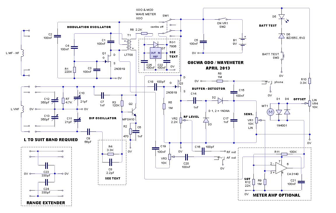
My design although called a grid dip meter is technically a transistor DIP meter, the name grid dip is historical and comes from the earliest meters of this type using valves, where the dip in a grid voltage/current was measured to indicate resonance. This name has historically been applied to instruments that do this function.
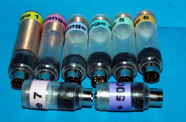
The coils are wound on 20 mm OD Perspex tube using 28SWG enamelled copper wire. The windings are soldered to a 7 pin din plug keeping the wires as short as possible.
Calibration can be done by using either a calibrated RF signal generator and using the unit as a wave meter or using a calibrated comms. receiver using the unit as a modulated oscillator to provide a signal.
Hope you find this is a useful design and enjoy building it, 73 for now de Nick G0CWA Any comments will be gratefully received and as usual I can be contacted by e-mail at the bottom of my projects page or via the Radio Board and QRZ forums as G0CWA.
Remember To Check The PCB Track Layouts And Mirror Them If Needed. I Have Presemted Them Aa “X-RAY” Views Of The Final Board !