G0CWA FET Tester Project
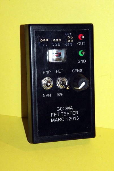


Firstly although this is my build of a go / no go RF transistor tester the actual design came from the excellent book “Solid state design for the radio amateur” published by the ARRL. The circuit is a Pierce oscillator to which the transistor under test is plugged into. The circuit includes switchable feedback settings using switch sw1 for different transistor types (FET or Bipolar) and a PNP (P-channel) or NPN (N-channel) selection and combined centre off power switch. It would also be a good idea to used different coloured led’s for the different polarities. I used my led’s to illuminate the meter movement giving an indication of power on.
The main purpose behind the tester is to provide a cheap dynamic transistor tester with no frills, most modern DVM’s have a bi-polar transistor test function, but commercial, or even homebrew, FET testers are few and far between. Although possible to test an FET using a DVM it can be a difficult process, this simple tester is easy, cheap and easy to use.
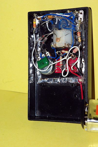
Unusually for my projects I have not included a PCB design as building “dead bug” style was far more convenient.
The diodes used were 1N34A’s but any small signal diode will do, the crystal was a surplus 20MHz unit but anything above say, 5MHz should be ok. The meter movement I used was a small battery test meter but any meter from 50 micro-A to 1mA FSD can probably be used. The transistor holders were “made” from a turned pin i.c. socket, a lot cheaper than standard transistor sockets. The final feature being an output socket so the output can be monitored on a scope etc., or even used as a simple signal source.
The transistor activity is monitored on a simple RF detector and analogue meter arrangement. This enables measurements of relative transistor performance amongst a group of transistors.
Please note power transistors may not work due to low gain and or low maximum operating frequency.
Sorry this one is so short and sweet a project but I am sure you will find it a very useful addition and a very cheap almost “junk box” piece of test equipment.
This is my second build of the circuit, the first was “liberated” by one of my friends as an addition to his equipment, and I found I missed it so built myself a replacement, including a padlock and chain to my bench!!!!!
I will be following this with other similar useful but cheap items of test equipment.
If you are into solid state radio home brew, the book mentioned is, to my mind, a must have as it is full of useful circuits and theory. I have found many a circuit or idea on its pages. Thanks to the publishers and authors.
I apologise if this write up is not to my usual standard but I have had a major relapse in my health but I can still be contacted with any problems via either the Radio board or QRZ forums (G0CWA) or by E-mail shown at the bottom of this page. Please be patient for replies as I am not back to my normal self and won’t be for quite a while.
Please only contact me via these routes if you have any questions, I can’t guarantee to reply otherwise as I can’t see every reference to my sets.
Enjoy the design 73 for now Nick G0CWA