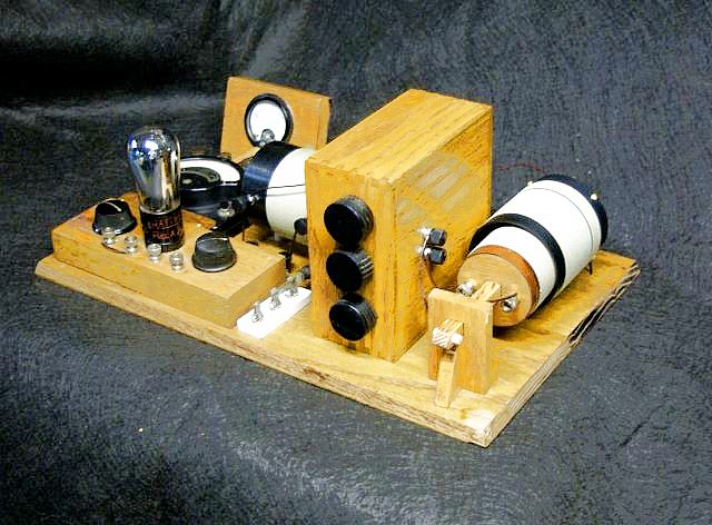
AI2V's 1912 Armstrong
Built by Pete, AI2V


Dave
Simple circuit: Series tuned antenna, parallel grid and plate tanks. No coupling between plate and grid. Variable caps are in the tall box. A UX 01-A was used only because I couldn't find a UV socket (it will be changed). A 00-A tube did not work well. The antenna coil slides on a square oak shaft inside the grid coil. The square shaft prevents rotation. Wood was used to maintain the highest Q. Except for the coils and filament wiring, all wires are #24 SCC monel, easy to solder and I have a huge spool of it. The spaghetti is made from running fiberglass sleeving (Mouser) through a puddle of acrylic paint. A 2K headset forms the cathode resistor. All coils are #28 SCC solid copper and Q's were nothing unusual.
The wood is all oak that has been "aged" to the period.
It works well for AM but more importantly in the Armstrong patented mode, a variable audio tone can be heard with a CW input by careful adjustment of plate and filament voltages and adjustment of tuning caps, with no RF input there's no audio. The audio is easily seen on a scope since I have lousy hearing. The stable audio range is around 700-1000Hz.
This project is for the 100th anniversary of the 1912 Armstrong patent; it will be going in the Radio Museum at InfoAge, Wall Twp, NJ. The Museum is run by the Antique Radio Club of NJ.
Just thought I would share ideas from a novice homebrewer; this is my first. I usually just restore basket-case AK breadboards.
Pete AI2V stateasylum@yahoo.com