G0CWA Analog AF/MF Signal Generator
2Hz up to around 200KHz, April 2013


Complete PDF file with schematics available for download
Introduction
Hi. Here is my design for a simple easily customizable signal generator generating variable levels of sin, triangular and square wave signals for setting up of filters etc with the added bonus of a 5v TTL compatible clock signal all from 2Hz up to around 200KHz. The whole unit is powered by either two PP3 9 volt batteries or, preferably, because of the relatively high current consumption a cheap (12V 200mA or higher) unregulated power supply. The cheap 12V wall wart types give around 15V+ peak.
Any supply greater than 14V to up to around 20V will do as the onboard regulators will take care of it.
I apologise for using an out of date chip for the design the ICL8038 although now out of production is still easily available on e-Bay or via a lot of component suppliers as it was a very popular chip. Take care though as you should expect to pay no more than £4.00 probably a lot less I got some from Hong Kong for £1.00 each, some people are asking for up to £50.00, yes £50.00. At present there is no SMT equivalent available. I chose this route rather than a DDS approach because it is far easier to reproduce as a “one off” home brew project.
Although for best performance ideally a split rail power supply should be used, a cheap split rail supply was not easily available so I designed the circuit by several simple “fiddles” to run on a single rail with an onboard synthetic Ground.
Broad SpecificationN
Power supply either 2x 9volt batteries internal or an external DC of 14-20V
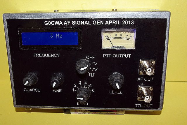
Frequency coverage 2Hz to around 200KHz in 6 switched ranges
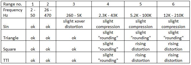
Sin, Triangular and Square wave outputs of up to around 3V PTP
5V TTL compatible clock signal
Optional Un-calibrated output level meter (guide to levels only)
Optional Digital frequency read out
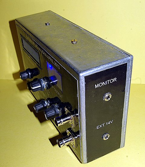
Output monitor socket
Modules
The generator is built in a modular format as are most of my projects, the minimum required is the PSU and main board calibrated dials will serve the same purpose and reduce cost.
The frequency meter module was bought off e-Bay from “jpl995” and was listed as FREQUENCY COUNTER 1HZ-80MHZ WITH 1HZ RESOLUTION
I found Jim was very reliable and helpfull. Others supply similar modules but I have not dealt with them.
PSU
There is nothing special here just a regulator chain made up of a 7812, 7809 and 7805 the whole unit being bolted to a die-cast box which provides sufficient heat-sinking and shielding. No insulating washers were needed as the “mounts” are connected internally to the OV rail
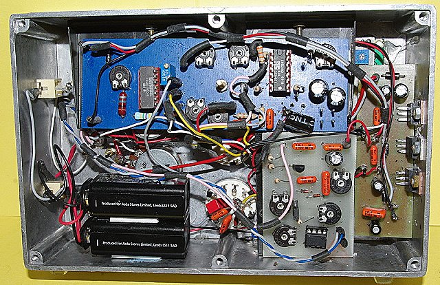
Main Board
Firstly an apology this board although basically the same as my prototype does have slight differences the major ones being on the right hand side of the board. My prototype had two extra op-amp buffers, one for the square wave signal and one for the output, I found neither were needed and removed them from the final layout, just taking the inputs to the simulated ground (5V rail).
The operation of the ICL 8038 chip is covered on its data sheet and is not discussed here.
Output Meter
The output meter is included for giving a visual display of the output amplitude of the signals and although it works on all modes is accurate on sin waves only, even then it is not particularly accurate and is intended as an indicator only. Accurate levels would have to be measured on a scope, but, it is still a useful addition enabling quick return to values.
Parts Sources
The frequency meter off e-Bay from “jpl995” and was listed as “FREQUENCY COUNTER 1HZ-80MHZ WITH 1HZ RESOLUTION”
The ICL8038 although now out of production is still easily available on e-Bay or via a lot of component suppliers, but watch the price, don’t pay more than around £4.00 maximum.
All the rest of the parts are standard ones and should be easily available.
This again was built to replace my original unit liberated by my friend who at the moment is building up his test equipment.
Hope you find this of use and happy oscillating 73 for now de Nick G0CWA.
Any comments will be gratefully received and as usual I can be contacted by e-mail or via The RadioBoard and QRZ forums as G0CWA.
I cannot guarantee to see your questions if posted elsewhere
REMEMBER TO CHECK THE PCB TRACK LAYOUTS AND MIRROR THEM IF NEEDED. I HAVE PRESENTED THEM AS “X-RAY” VIEWS OF THE FINAL BOARD !!!!
I do not supply kits, parts, PCB's or build boards for my projects but am more than willing to help talk you through a build or fault finding via my normal contact methods, or even SKYPE if required for direct contact.
PS. I have ordered some ICL8038 chips off e-bay from janeh2100 and they cost £4.36 for 6. They arrived this morning and seem to be perfect, they work anyway, don't expect instant delivery though the postal system is ssssslllllllloooow !
Complete PDF file with schematics available for download