Dave's All Wave 1625 Regen Radio
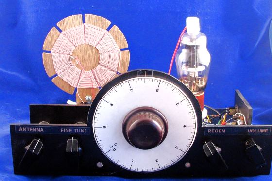


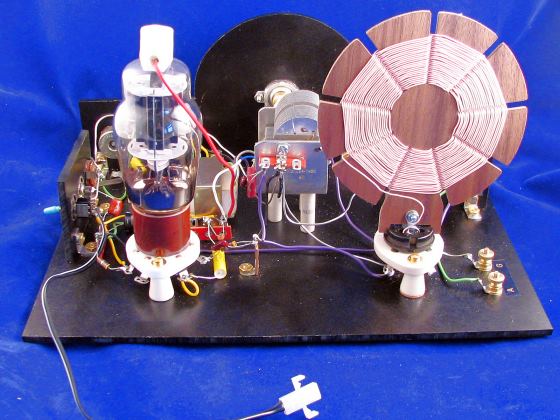
Hi Friends. Here is my latest wonder radio, an all-wave set built with a 1625 tube. This is not my first 1625 radio. Others included my #58 converted crystal set, and my #63 multi use set. You might say that this is my first tube only 1625 radio. Why use a 50 watt transmitting tube in a set like this? First, it really looks cool. The tubes are cheap, and they work well as a regenerative receiver with only 12 volts on the plate. They can be operated with a common wall wart power supply. Since I like multi-use projects, I decided that this radio should be an all-wave set. I made coils for the long wave band, medium and short wave bands.
The coils are spider types. They work very well for this purpose, especially the MW and LW coils. They have a lot of turns of litz wire and the size of the form makes it easy to make. The shortwave coils could have been made with cylinder coils. This might have been an advantage because there is a small hand capacitance problem caused by large spider shortwave coils. One other concern is that the coils must pry out of the socket gently. Pulling on the top of the spider will separate the form from the plug. The form is attached to the socket with an insulated ring terminal glued into the plug base. Given these conditions, I am not unhappy with using this kind of a coil and I intend on doing it again. (Turning the coils 90 degrees would most likely reduce the hand capacitance effect.
The main tuning capacitor is a dual section 270 pf type. This is a surplus unit, but is still available. It features a 2:1 vernier drive. When added to a 6:1 vernier drive there is a 12:1, or 6 full knob turns tuning advantage. The slower the tuning is, the better. This is especially true on shortwave. One construction note: I have a wire running from one of the vernier drive mounting screws to the frame of the capacitor. In this case, the capacitor shaft is plastic and I wanted to reduce hand capacitance problems.
The two sections of the variable capacitor are used in different ways, depending on which coil is plugged in. When the shortwave coils are used, only one section of the capacitor is used. A 360 pf capacitor is place in series with the variable to reduce the capacitance to around 160 pf. The value of this fixed capacitor was selected so that when the MW coil was plugged in, the tuning would cover the full band. But I also wanted reduced tuning ranges on SW, for easier tuning. If you only desire shortwave coverage, a single 140 pf variable could be used instead of the dual capacitor.
On the MW and LW bands, the second 270 pf section is connected. This is done by shorting two pins on the coil plug as shown in the coil table below. I have to tell you that the long wave coverage was actually an afterthought. I had a larger coil form and some small litz. I am not unhappy with my decision. It has prompted me to build more robust long wave coils on larger forms.
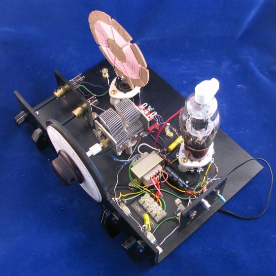
There is a line out connection on this little radio. This is to connect to an external audio amplifier. I used a Bogen T725 matching transformer in this project, as I do in a lot of my projects. By selecting the best tap, I feel that I get the most from this circuit. I used a 5 circuit barrier type strip to make it easier to select the tap.
I used a 12 volt wall wart type power supply for this project. It is very safe and cheap. The current requirements is 500ma. Due to what I believe are some ac leakage issues, there is some distortion when listening to cw or ssb stations (oscillating mode). I have a set of gel cell batteries and found the reception was much cleaner. You may want to consider battery operation if you are going to use this for ham radio reception. Another thought is to run the heater ungrounded with the wall wart and the rest of the set on a couple of 9 volt batteries .I haven't tried this though.
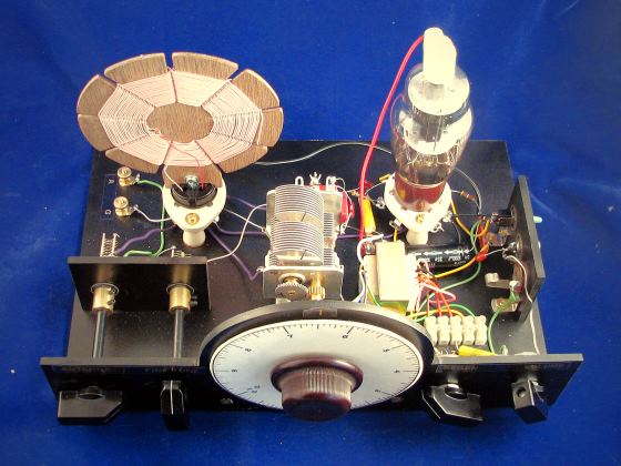
Good wiring practices were attempted in this project. I thought that a central ground
point was essential. That point is the variable capacitor frame. All
my grounds lead to that point. I'm not sure if this helped, but it didn't hurt.
My little radio is built on 3/16 inch thick (about 4,5mm) and 12 inch (30cm)
wide Garolite® sheet. The depth of the base is 8 inches (20cm). The height of the front panel
is about 5 inches or 12,7cm. The capacitor is lifted off the base by three 1-1/4
inch (3.2cm) ceramic standoffs. The ceramic standoffs are not necessary in this
case, but I like how they look. The two sockets are raised by standoffs too.
There are two other pieces of Garolite® added. One is to mount the antenna and fine tuning capacitors away from the front panel. This reduces hand capacitance problems. Make sure to use plastic or wooden dowels to the knobs. The other panel is for the power switch and output jacks. I didn't have a good place on the front panel for these items.
Building a set like this on an aluminum chassis is encouraged. I like building my sets on the old time looking Garolite®. If you are a long time visitor to my site, you will know that while I believe performance is very important, building a nice looking radio has become an interest of mine. So I hope you forgive me for being a show off.
Before you go, take a look at a project based on the 1625 All-Wave shown here. Nick Strong, G0CWA built this one valve all wave regen set. Have a look. Nick added some of his own ideas in to his design.
Happy building de N2DS!
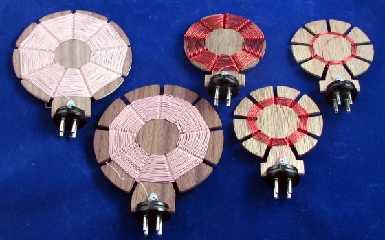
                                     Spider Coil Data
            Mhz                 Inches
         Frequency     uh    Wire    ID    OD   Turns   Tap     Notes
         .2  -  .53   1260   30/44  1.5   5.0   125      15 Short pins 3 + 4
         .53 -  1.7    197  100/44  1.5   5.0    50       5 Short pins 3 + 4
        1.75 -  3.5     44    22    1.5   4.0    24       6
        3.45 -  7.5     12    22    1.5   3.5    13.5     6
        6.8  - 15.2      3    22    1.5   3.5     7.5     2
Parts List, Dave's All Wave, "1625" Special:

Qty.	Part					Source

1	Garolite®, 12" x 8" x 3/16"             MC
1	Garolite®, 12" x 5" x 3/16              MC
1	Garolite®, 3-1/2" x  2-1/2" x 3/16"     MC
8	"L" brackets, .625" x .625"           MSR
4	Small Knobs, your choice              MSR
1	Large Knob, your choice               MSR
1	Styrene Disk, Round, 4-1/2"           HDW
1	Vernier Drive, 6:1                     DS
1	Switch, SPST, On-Off                  LDS
1	Jack, Headphone, to match plug        LDS
1	Jack, RCA-Phono, Line-Out             LDS
2	Dowel Rod, ¼" x 4" L                  HDW
2	Shaft Couplers, 1/4"                  LDS
2	Thumb-Nuts                             DS
4	Standoffs, 6-32 x ½"                  LDS
3	Standoffs, 6-32 x 1-½"                LDS
3	Terminal Strip, 3-point               LDS
1	Terminal Strip, 1-point               LDS
1	Variable Capacitor, Dual-Gang, 270 pf LDS
1	Variable Capacitor, 30 pf             LDS
1	Variable Capacitor, 5 pf              LDS
2	Potentiometer, 5k ohm                 MSR
1	Tube Socket, 7 pin                     DS
1	Plate Cap                              DS
1	1625 Tube
1	Tube Socket, 4 pin                    LDS
 5      Spider-Forms, See Text
1	Transformer, Bogen T725                DS
1	Eurostrip, 5 Terminal                 LDS
1	Resistor, 470 ohm, 1/2 Watt           MSR
1	Resistor, 4.7 M-ohm, 1/2 Watt         MSR
1	Capacitor, Mica, 22 pf, 50V            MSR
1	Capacitor, Mica, 360 pf, 50V          MSR
1       Capacitor, Disc, 0.001 uf, 50v        MSR
1	Capacitor, Disc, 0.01 uf, 50V         MSR
2	Capacitor, Disc, 0.1 uf, 50V          MSR
1	Capacitor, Elec, 1.0 uf, 25V          MSR
1	Capacitor, Disc, 1,000 uf, 25V        MSR
	Misc. screws, nuts, lock washers      HDW

Sources:

DS: Contact me
MC       McMaster-Carr
            http://mcmaster.com
LDS:   	Leeds Electronics, 1-718 963-1764,
          	http://www.leedselect.com/
MSR:	1-800-346-6873 or http://www.mouser.com
HDW:  Local Hardware Item