Darren's Downunder Diode Delight
(Crystal Radio #2)
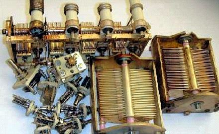


It started by looking around on ebay for parts — ended up with this lot. This was a great find. Never used and silver plated. The two 40-550pF capacitors were exactly what I was looking for. Let the fun begin.
What kind of Radio to make?
More internet research and fascination with 'spider heaven' soon had me inspired and learning. Here are some of the many sites I stumbled across:
Another brilliant site, learnt lots here.
Experiments with Coupled Circuits
LC Tuned Circuit Resonant Frequency Calculator
What have I learnt?
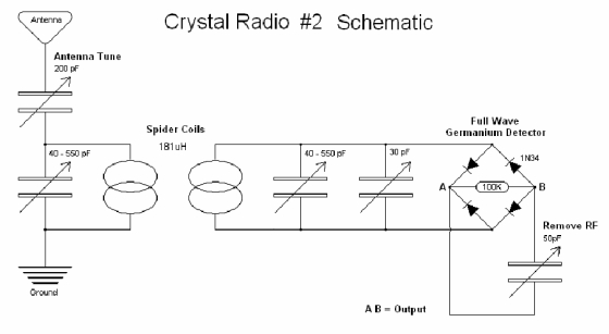
Internet research and my experiences with #1 resulted in the following schematic:
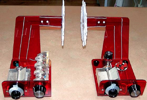
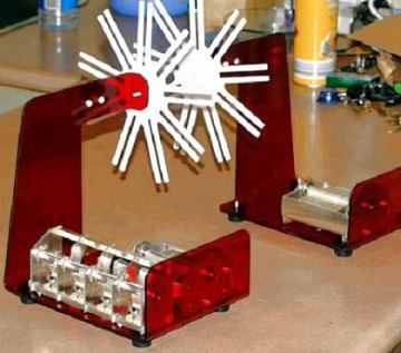
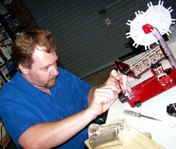
Construction
The red plastic used to be an old LED sign. I decided on plastic on reading the moisture in wood impacts the Q. Bending was done using a 70W bar heater and heat proof material producing a strip of heat. Cutting, filing, and construction completed. I then started planning layout and manufactured the spider coil formers.
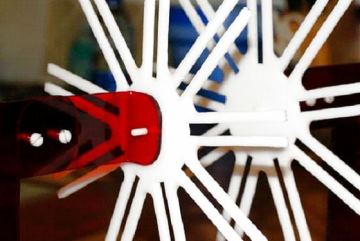
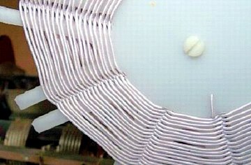
The Spider Coils & Calculations
I used Litz wire, kindly donated by David on a 'Shed Night'. The Litz wire is made up of 25 X 0.13mm strands. I used this cable diameter calculator to work out diameter of this multistrand litz wire:
The diameter of the 25 X 0.13mm Litz wire = 0.65mm or 0.0256 inches
The inside diameter of the spider coil former = 2.376 inches
LC Tuned Circuit Resonant Frequency Calculator to determine I needed 181uH and entered into Dave's Spider Coil Calculations
   Turns    uH         40pF      550pF
   39.5    181.3892    1868kHz   503kHz
   40.0    185.9717    1845kHz   497kHz
   40.5    190.6163    1822kHz   491kHz
   41.0    195.3233    1800kHz   485kHz
As highlighted 181uH (39.5 turns) should give me approx 503kHz to 1868kHz.
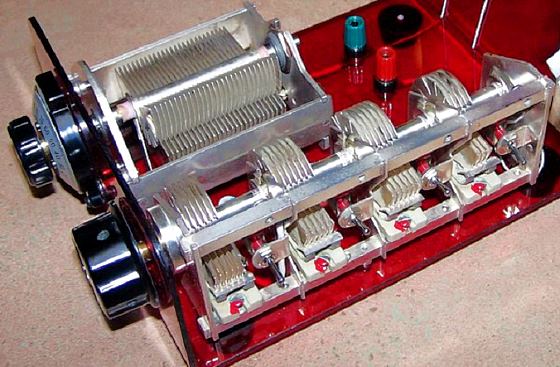
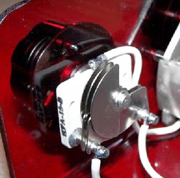
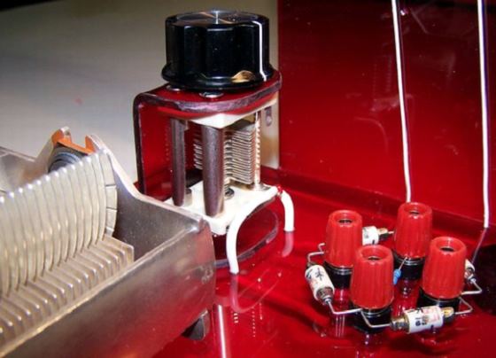
The Antenna Tuner Module
As Dave suggested via email I used the 4-gang for the antenna tune capacitor. After removing the ceramic coils 4 switches were placed on the existing tabs to switch in each capacitor as required.
The Detector Module
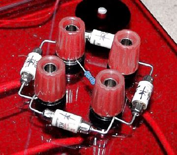
I decided to stick with my Full Wave Bridge configuration and sourced some 1960's 1N34 diodes on ebay. (US$1 each) There is a 100k resistor through the centre. This is where I connect my Amp Module as built with Crystal Radio #1. I don't really know the value of the Fine Tune Capacitor. On weak stations it adjusts the frequency by 5 on my Vernier scale.
The Capacitor to remove RF. This is the only part of my radio that doesn't seem to have any effect whatsoever. It's included in the schematics of the radio's I've based my design on. If anyone has any further information regarding this capacitor I'd be interested as it's a mystery to me.
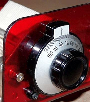
The Vernier dials were bought from Minute-Man.
How does it work?
Brilliant — Not only do I get 11 of the Sydney AM stations, I am able to separate them all. This radio is very selective. The variable coupling between the spider coils works a treat helping to pull in the weaker stations.
Stations Received and Tuning
   Antenna Tune Dial / Detector Dial = Frequency … Station Name

   92/92 =  576kHz — Radio National - ABC
   82/86 =  630kHz — News Radio - ABC
   75/75 =  702kHz — 702 ABC Sydney - ABC
   54/59 =  873kHz — 2GB Maquarie Radio Network - News / Talk
   46/55 =  954kHz — 2UE Southern Cross - News / Talk
   40/50 = 1017kHz — 2KY Sky Channel - Racing / Sports Radio
   31/41 = 1107kHz — 2EA Special Broadcasting Service (SBS)
   27/37 = 1170kHz — 2CH Maquarie Radio Network - Easy Listening
   22/35 = 1224kHz — 2RPH Radio Print Handicapped Network
   21/31 = 1269kHz — 2SM Broadcast Operations Group - Easy Talk / Sport & News
   05/21 = 1476kHz — Cool Country 2KA - Country Music
If your building or thinking of building a Crystal Radio — Have fun — It's a rewarding learning experience. But be warned — Also addictive (hey Dave) Please e-mail me with your comments.
Hi Darren. Thank you for submitting your beautiful radio for
publication on my visitors projects page. Looks like you have a winner there.
Dave