My Other Restoration Project
Dave's Homemade Radio Restoration Project
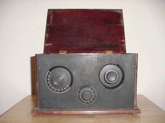
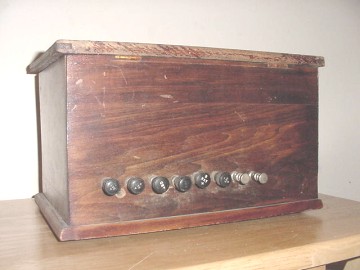
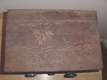
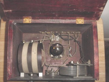
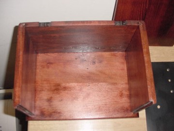
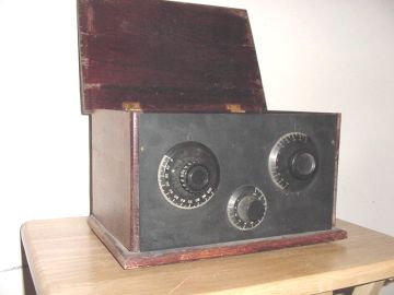
Old radio restoration. This is the "before".


Starting The Restoration Project
I have switched gears! 2002 has been a banner building year for yours truly. So far, 7 crystal sets and 3 tube sets. My next homebrew project will be a 2 tube broadcast receiver using types 32 and 34 tubes.
But, here is my restoration story. Earlier this year my friend Jack Aber, K2IZA learned of my new found hobby of old radio building. At the time I was doing only crystal sets. But Jack gave me this old homebrew tube set. I was very thankful as I never owned such an old radio. However old tube sets were unknown to me and I was involved in building the crystal sets. I left the radio in the living room, showing it to my guests. It was not cleaned up and the correct tube was missing. So it sat for 3 months before I had any idea what to do with this radio. I found an 01A tube on Ebay. I thought that this would be a good tube to use as there are a lot of them around, and it was entirely possible that an 01A was originally in this set. After I received the tube, I plugged it in, hooked up the voltages and fired it up. It didn't work very well, but it received a station! Wonderful!
At that point, I decided that I would do a full restoration. This will include taking the radio apart, cleaning all the parts, obtaining new hardware where needed and sanding and finishing the cabinet. I have no information about this set except for the circuitry. But I believe that this set was probably built between 1922 and maybe 1930. The circuit was very strange indeed. (I will provide it later). This radio is the regenerative style.
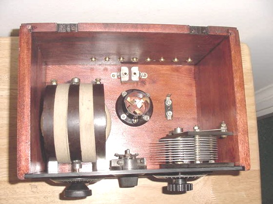
The parts consist of a tube (01A type), a bayonet tube socket. A grid leak resistor and socket, a 250mmfd fixed capacitor, a filament voltage rheostat, a tuning capacitor and a variometer. A variometer consists of an outside coil and a rotatable coil. The coils are connected in series and the resulting inductance will be the inside coil plus the outside coil to the inside coil minus the outside coil. The "mutual inductance" number (less than unity) also figures into this. I built a variocoil which is a cousin to the variometer.
Please follow me through this project.

The One Tube Radio Before Restoration.
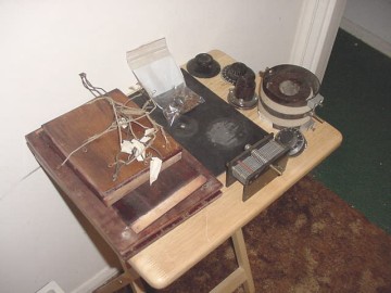
Old radio restoration. This is the "early during".
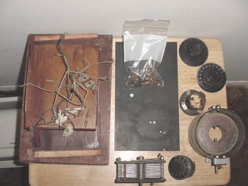
Taking it Apart
I have now disassembled the radio. I first drew
a pictoral of how the set was wired. I then began to take out the
wiring, marking each wire. I am planning on using new (but old) wire
however, I would like to keep it as close to the way it was built over
75 years ago. I wasn't planning on putting a CD player in this!
I then took out all the parts and carefully set them aside. The hardware
on the back was next. I decided to use new screws for the outside connections
when I rebuilt this set.
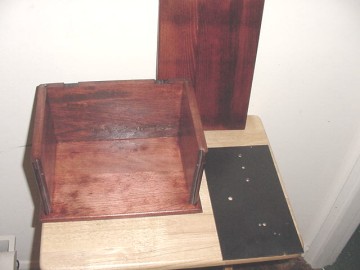
Then the sanding started. I first was doing it by hand, but then I thought it was time I purchased an electric sander. All the pieces were sanded to remove the old stain. It looked like the bottom piece was cherry wood, but the back looked like a different type and the sides and top still another!
I decided that I would use Minwax Red Oak stain to finish the entire cabinet. There are two coats of stain and several coats of shellac. This will give it some luster. The front panel is some kind of black bakelite material. It is very similar to the garolite that I have been using for my homebrew sets. This was very dull and I wasn't sure how I was going to clean it up. I took a Scotchbrite sanding pad and tested it on the back. It really worked nice, so that problem was solved.
Below you can see that I have started to assemble the cabinet. This is pretty easy. I used a little glue to hold the pieces together and the small nails also keep everything in place.
Next I will screw down the tube socket, capacitor and grid leak resistor holder. I will also put the screws through the back panel for the headphones and batteries.
All stained and ready for assembly.
Old radio restoration. The parts are mounted!.
Reconstruction
It sure is taking shape. I have cleaned all the parts and mounted the components. The front panel has not been attached. That will be done after the wiring has been completed. I did purchase new brass screws and washers for the back terminals. I cleaned the fixed 250mmfd condenser (capacitor) and mounted it with the original screws. I cleaned the hinges and screws with sandpaper. The screws weren't brass, but for now I will use them as they were original.
I thought of mounting the front panel in a better way. The person that built it had two little wood screws along the edge of the front panel. I thought that I would drill two new holes, use brass fillister head machine screws and a couple of brackets. I decided that I would stick with the original. What the heck, it stayed together for 75 years, why should I change it?
I am really pleased how this is turning out. There is a slight
problem in the top's front corners. I think I will put a small amount of
stain in the place where it shows. That will work for now until I find
out more about wood restoration. After all, I specialize in the circuitry
and not the wood work.
Next comes the wiring and the final assembly and testing.
The original wiring of this old radio.
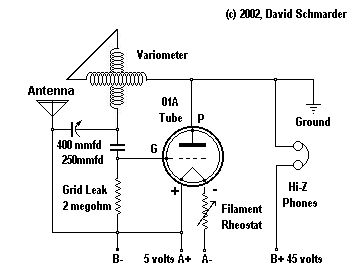
The Circuit, a discussion.
Yes, this radio did work before I took it apart and yes, this is how the radio was wired. I checked it several times because I didn't believe it. The use of the 01A tube is only a guess. The tube socket is one of those bayonet types. The tube has a small little pin sticking out the side. There was a socket adaptor insert for tubes with smaller pins and there were a couple of tubes in the cabinet. But the tubes didn't fit the socket. So I decided to make my guess. A type 30 tube would also work in this circuit. I did make one circuit change. In my homemade radios I discovered that the grid leak resistor should go to the A+ terminal rather than the A-. So I am making that change.
First thing I notice is the parts count. There ain't much to this puppy! If compared with one of my homebrew radios, it is missing the bypass capacitor and rf choke.
Perhaps the oddest part about this radio is now the plate of the tube is grounded! I guess there is nothing wrong with that as long as the voltages between each tube element is what it should be. It is just odd. Looking further, the plate voltage appears between the antenna and ground. Again, kind of odd. The wire between the antenna and the tube filament looks like it serves no use. Again, perhaps a wiring error. I will test this radio with and without that connection.
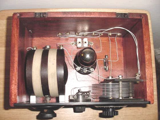
The Radio Is All Wired!
Done!
It's done! This has been a very nice project. Thank you for hanging in there through the five pages.I think it was worth fixing up this old homemade radio. Maybe in another 75 years someone else will be re-restoring this set. Gee, I wonder if AM radio stations will still be around? Maybe a handful of clear channel 50,000 watt kilocycle factories will still be out there.
I wired this radio with 20 gauge enameled cotton covered wire.
The original was 18 gauge and I don't think it was enameled. So here
and there I did deviate from the true 1920's restoration. The rubber feet
attached with a screw instead of being a tack bumper. I did wire it
the same electrically but slightly different mechanically. I just
didn't like the way that the original builder wired the set. I did
leave in the extra wire that I discussed on the last page.
Does it work? It sure do! I picked up only one
station tonight but it came in loud. I used three 1.5 volt D cells
to light the tube and the five 9 volt batteries for the B supply.
This old radio does now work better than when I started. I might
look for the older balloon style 01A tube to replace the ST type, but
that isn't important now.
Again, I want to thank Jack Aber, K2IZA for donating this radio to my cause. Guess it keeps me out of the bars but not out of Ranger Bob's garage.
73, Dave - N2DS
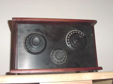
Before & After
Radio restoration Links
The Radio Attic
Phil's Old Radios
Pat's Old Radios
Antique Radio Forum