Spider Coils
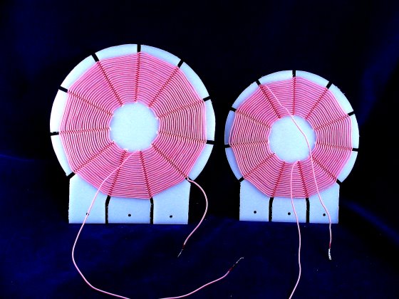


Welcome to my spider coils page. As you might have noticed, this is my favorite coil. They are easy to make, adjust and to use. I have always preferred them to cylinder wound coils. Below I have the formulas for calculating your own coils, as well as some examples.
A cousin to these coils are the spider contra wound coils. They are somewhat difficult to understand at first, but they are a technological breakthrough. But for the meantime, please read on here.
Spider Coil Calculations
To calculate your own coils, here is some information and a few tips.
The main formula is L=(r*n)^2 / (8r + 11b), with L = inductance, r = mean radius, n = number of turns and b = coil depth. The means the inductance is equal to the mean radius times the number of turns squared divided by 8 times the mean radius plus 11 times the coil depth.
On the face, this is a little hard to work with if you are
making a coil. If you have a coil and want to find out the inductance, this
formula is fine as all you need is a ruler and to count the turns.
For us radio builders, the best place to start is to input
the number of turns, the inside diameter of the spider coil and wire
diameter. There is a glitch that was found concerning litz wire diameters
which I will discuss later.
A spreadsheet or a programmable calculator is very handy for calculating the coil. I used the Lotus 123 program to make my spreadsheet. Below are the values and relative cell values. All this is based on the original formula that is shown above. I am much better at winding coils than I am the math, so please check this out.
    cell   name               formula
    ____   ____               _______
     C4    Wire diameter      Input this value
     C5    Number Turns       Input this value
     C6    Inside Diameter    Input this values
     C7    Coil Depth         (C4*C5)
     C8    Mean Radius        (C7+(C6*0.5)+(C6*0.5))/2
     C9    Outside Diameter   (C7*2)+C6
     C10   Inductance         (((C8*C5)^2)/((8*C8)+(11*C7))) [The main formula]
     C11   Wire Length        (C5*C8*2*3.14)/12
                              [Add a little more wire for connections]

 Length measurements are in inches, inductance in µH.
When winding spider coils with thin wire strand gauge size such as the 660/46, there was a difference found between the calculated coil depth (wire diameter times number of turns) and what the coil actually turned out to be. This drove a couple of us nuts until it was discovered that when a spider coil with litz is wound, the windings are compressed at the crossing points.
It was found that the diameter worked out to 15 to 18 percent less than the manufacturers data. This is not a problem in cylinder coils, only the spider coils. So instead of using 0.055 inches as a diameter, 0.048 was used.
Reducing the value of the wire diameter by 15% will give you a closer value of the outside diameter of the coil and a closer tolerance on the coil. Plugging in the two values (.055 vs .048) only makes about a 1.5% difference in the coil inductance. The wire length and outside diameter change quite a bit using the different diameters. Make the spreadsheet and plug in the numbers and check it out for yourself.
In the few instances that I have wound the coils using the spreadsheet and comparing the results with the L/C meter, I found that the calculated value ends up very close with the real world value.
At this time I am keeping this page open. I invite comments and especially corrections to any data in this section.
Feedback E-Mail
Dave, I found your webpage while searching for a formula for determing the number of turns for a given inductance of a spider web coil. The formula on your page is fine but isn't too practical if you want to build a coil to a specific inductance. Well, I used your formula to derive a formula for determing the number of turns required. After some math manipulations I was able to get what I wanted. The formula was checked for accuracy throughout the range of 1uH to 2000uH. The results agreed with the original formula. At first glance, the formula looks overwhelming since it is a quartic equation ( a 4th degree polynomial), but with the "Quartic Equation Solver" available for use at www.akiti.ca/Quad4Deg.html, it is a piece of cake to solve.
The formula for determining the number of turns required for a given inductance of a spider web coil is: w^2x^4 + 4rwx^3 + 4r^2x^2 - 60Lwx - 32Lr = 0
  Where    x = number of turns to be determined
           w = diameter of wire (inches)
           r = inner radius of coi (inches)
           L = desired inductance of coil (uH)
Enter the values for w, r, and L in the above formula; do the indicated multiplications and the formula will then appear as: Ax^4 + Bx^3 + Cx^2 - Dx - E = 0
A, B, C, D, E represent the results of the multiplications. Now take these values (don't forget that D and E are negative) and plug them into the similarly labeled boxes in the quartic equation solver. Press the "calculate solutions" button and it will spew out the results. Since this is a quadratic equation, there will be 4 answers displayed. The correct answer will be obvious since it is a positive number, the other 3 will be either negative or complex.
George Miller, W4DNW (ex DL4ADP)
Spider Coil Examples
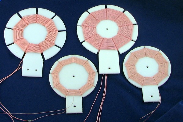
Here are some actual measurements of some coils that I have made. I will add to this table as I make more coils. These inductances are a little larger than you usually see. This is because I build the coils a little larger so I can take a little wire off if needed to trim the coil to the circuit. The lengths are in inches and feet
A little note about my Q numbers: These numbers were reached using my unverified HP 4342A Q meter. Since I made the measurements on the same machine using the same methods, I will stand by the numbers inasmuch as they relate to one another. I do not make any claims of these being actual Q values. I have measured a limited number of coils using the old manual method that I used to use before getting the Q meter. They do fall in line with what I have measured on the HP. I do, however find that my numbers are in the ball park with others that have measured the Q of similar coils. So please take them on your own beliefs.
  L µH   Thickness  I.D.   O.D.  Litz Size  Turns   Length  Q-1Mhz   Cself

  154       .125      2.25   3.50   40/44     40      32ft    330   4.7pF
  248       .125      2.25   3.50   40/44     46      40
  225       .125      1.75   3.50   40/44     56      38ft    340   3.5pF
  248       .125      1.75   3.50   40/44     58      40ft    375   3.7pF

  149       .125      2.25   4.75  100/45     39      33ft    540   6.3pF
  238       .125      1.75   4.25  100/45     55      42ft    620   5.4pF
  241       .125      2.25   4.75  100/45     49      42ft    620   5.4pF

  146       .125      1.88   4.25  165/46     42      34ft
  200       .125      1.88   4.25  165/46     48      38ft
  220       .125      1.88   4.25  165/46     51      42ft
  232       .125      1.75   4.75  165/46     55      44ft    750   4.0pF
  250       .125      1.88   4.25  165/46     54      45ft
  250       .125      2.25   4.75  165/46     49      45ft

  155       .125      1.88   6     630/46     40      43ft
  244       .125      1.88   7     630/46     49      62ft

  150       .125      1.88   6     660/46     39      42ft   1000+  4.7pF
  241       .125      1.88   7     660/46     48      60ft   1000++ 3.0pF
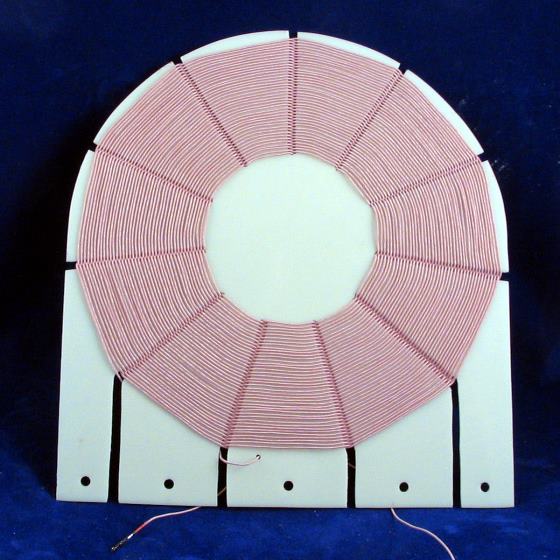
Long Wave Coil
A few weeks ago, while experimenting with the long wave coil I made for my 1625 tube all wave set, I discovered that I was able to hear some European broadcasters. Most of the time it was just hearing a heterodyne whistle, but I did clearly heard a station too. That is what it took to get me started on a dedicated long wave receiver.
I needed a coil, and it had to be big. I had a styrene coil form left over
from my first large styrene coils that I made. Since I had switched to a smaller
hub (as well as an overall smaller coil), this form wasn't needed.
I used 60/40 litz. That is, 60 strands of
40 gauge wire. 40 gauge works the
best between 100 and 200 khz. My upcoming receiver design will be designed to work
at 100 khz but should tune up to nearly 500 khz.
My coil form is made from 1/16 inch (1,5mm) thick styrene material. The hub is 3 inches (7,6cm) in diameter. The width of the form is 7-3/4 inches (19,7cm). I wound 80 turns on the form, filling it nearly to capacity. The resulting inductance came out to be 992 microhenries. My target was 1000 µH. 81 or 82 turns would have done it! But close enough.
We'll see how this works when the band opens again.
How I Make My Coils
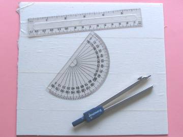
The first step is to cut a piece of HDPE (high density polyethylene) to the size needed. You will need a protractor, ruler and a compass to lay out your form. (hint: If you expect to make a lot of forms, make one as a master template to trace others) The width of the form is determined by the diameter of your proposed coil. The height the same as the width plus 3/4 to one inch additional (18-24 mm) to accommodate the mounting area.
Cover the entire piece of HDPE with wide masking tape. Draw a vertical line that divides the width in half. Measure the width and divide by two. Then measure down from the top. This point will be the center of the coil, except for the mounting area. Use the compass and draw a circle to the full width of the form. You may have to darken the line by hand drawing. It depends on the hardness of your compass lead. Then make another circle for the hub size.
Now is a good time to make a line across the bottom of the form that is about 3/8 inch (9 mm) from the bottom. The mounting holes will be located along this line.
Next figure out how many degrees each slot will be positioned at. You may want to cut a circle of paper and do the layout there. Spider coils must have an odd number of slots to function. The number really depends on the mechanical aspects of your form. I like to have as many slots as I can get, being careful that the distance between slots at the hub are not too close. That would seriously weaken the form. With a 2 inch hub (50 mm), I like to use 11 slots.
Lay out the center positions of the 11 slots. Measure to the left and right for the width of the slits. I like 1/8 (3 mm) to 3/16 inch (4 mm) spacing when making a form for 660/46 litz. 1/8 inch is plenty for 165/46 litz and a little thinner than that for 40/44 size litz. If you are making a tracing template, make the slots a bit wider.
Once the slots are laid out, there are some at the bottom that have to be extended so that the wire will fit as you are winding your coil. You can go straight out or use an angle like I do.
Now find the positions of the 4 holes (or how ever you want to do it) and drill the holes. The hole size will depend on the screw size you will use.
Next cut the rounded top of the form with a scroll saw. Then carefully smooth the edges with a small belt sander.
Carefully cut the slits with your scroll saw. If you are familiar with
your saw, I'm sure that the outcome will be pleasing. After the form is cut,
the tape can be pealed off and you are ready to wind the coil.
The wire is then wound. I like to put the supply spool at a
distance of about 10 feet (3 meters). That will give room for the wire to twist as
it always does a little.
As you are winding, count the turns. When the coil is finished, count again before cutting. When I have a fixed amount of wire, that is close to being the right amount, I wind the first coil (if the two are different size, wind the bigger one first). Then I unwind all the wire from the supply spool, and wind the other form starting at the other end. I try to end up with a turn or two extra and when the windings on both coils are correct, then I make the cut. When the coils are installed and working, turns can be trimmed depending on your own antenna and variable capacitor situation.
If using a 365 to 400 pf capacitor, you want the bottom of the band to tune when the capacitor is nearly meshed. I make my sets tune to 520 khz at the bottom. The top usually ends being at the correct nearly open capacitor. The low distributed capacitance of a spider form will allow tuning the entire band without adding parallel capacitance for the bottom of the band.
Spider Web Coil Links
Gollum's Spider Coil
Gollum's 2 coil dx receiver
Gollum's shortwave spider radio
Mike Tuggle's Spider Coil
Formula for calculating spider coils