Analysis of the Tuggle Front End – Part IIIAs a first approximation, the 3dB bandwidth of
the antenna-ground-lossy tuner system under matched load conditions can be
computed assuming that the L1-C tank behaves as an equivalent constant
inductance Leq in the 3dB passband, this inductance being in series with the
rest of the circuit. However, this approach leads to large errors in the
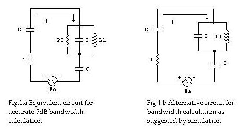
results, as suggested by a SPICE circuit simulation. A precise model for accurate bandwidth computation
is shown in Fig.1.a below. RT is the net RF resistance in parallel
with the L1-C tank at w = wr , as found in part II of our study. Ground
losses Rg and antenna radiation resistance ra are accounted for by
r. However, calculations on this circuit are rather tedious. Simulation shows
that the circuit depicted in Fig.1.b can be alternatively employed for
bandwidth computation with equivalent results to those given by the circuit of
Fig.1.a. Here, Re = 2Rs1 (please refer to part II). Circuit
calculations in this case are much more simple.
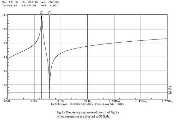
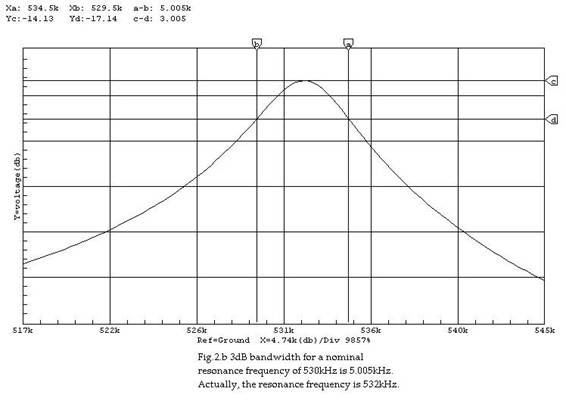
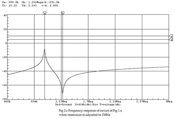
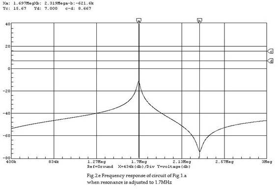
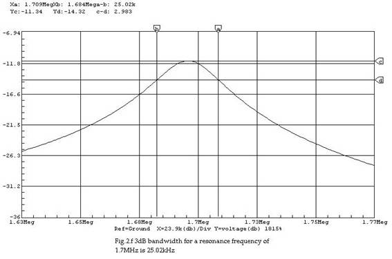
Simulation resultsFigures 2.a through 2.f illustrate simulation
results for circuit of Fig.1.a at resonance frequencies of 530kHz, 1MHz and
1.7MHz. Assumed values for r and Ca are 30 ohms and 200pF, respectively. The
values for RT are those obtained when the secondary load R2
is impedance matched to the primary side (please refer to part II). Notch
frequencies occurring above resonance can be observed on the graphics. The Y
axis represents voltage across r in decibels with Ea being a 1volt-amplitude
unmodulated carrier.
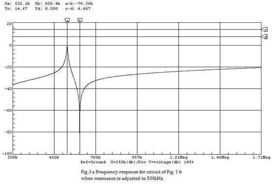
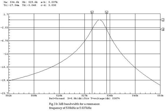
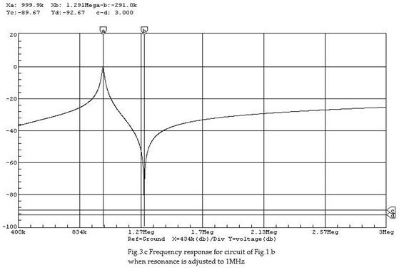
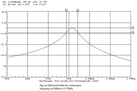
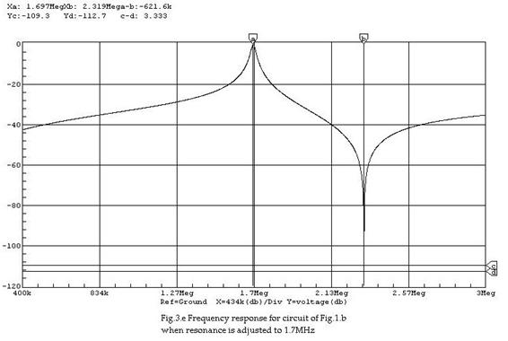
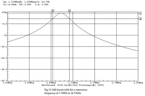
Figures 3.a through 3.f show simulation results
for circuit of Fig.1.b at resonance frequencies also of 530kHz, 1MHz and
1.7MHz. Again, r = 30 ohms and Ca = 200pF. Re = 2Rs1 , and it can be easily
shown that:
The Y axis on the graphics represents voltage
across Re in decibels, with Ea being a 1 volt-amplitude unmodulated carrier.
3dB bandwidth calculations We shall now proceed to calculate the 3dB
bandwidth of circuit of Fig.1.b. Mesh current is given by: where: The amplitude-frequency relationship for I is
determined by: At the -3dB points: The corresponding frequencies must satisfy the
equation: or:
Let wr be the resonant frequency and w = wr + Dw the frequency at a –3dB point on the amplitude
curve. The left hand member of eq. (1) can be written as: with the following approximations:
Then: or: which simplifies to: Now, if wrCTRe<<1, then: this is:
From part II of our study we can obtain the
following expression for Rs1: Then, the 3dB bandwidth is given by: in radians per second. Next, we shall compute the bandwidths at three
frequencies: 530kHz, 1MHz and 1.7MHz. Results are tabulated below.
Results for BW are very close to those obtained
from simulation of circuit of Fig.1.b.
Ramon Vargas Patron
Lima-Peru, South America
April
11th 2004 |