Analysis of the Tuggle Front End
This
article analyzes the Tuggle tuner, of common use in
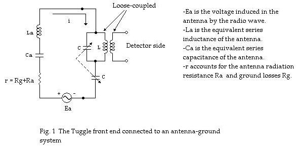
high-performance DX crystal sets. An equivalent circuit for the antenna-ground
system with the tuner connected is shown in Fig. 1 below. It must be recognized
that there is some stray capacitance of the rotor and frame of the two-gang
variable capacitor to ground. This should be shown as a fixed capacitor across
the bottom variable capacitor. Its presence will reduce the maximum frequency
to which the circuit will tune. However, in the present analysis this stray
capacitance is neglected.
The
mesh current is described by:
 …(1) …(1)

where:


or:
Then, I = IMAX when:

This is, when:
 …(2) …(2)
which is satisfied at certain radian frequency wr.
At this frequency, the L-C tank circuit behaves
as an equivalent inductance

Usually, L is much greater than La
for antennas used in crystal set work. Then,
Equation (2) can be written as:
We can then write:
After some algebraic manipulation we obtain:
 …(3) …(3)
The equivalent capacitance resonating with L
is:
Clearly, Ceq>C.
Following is a numerical example illustrating
the use of the above results.
Let C be a variable capacitance with CMIN
= 20 pF and CMAX = 475 pF. Let also Ca be
200 pF. Then, Ceq varies between
CeqMIN = 38.18 pF and CeqMAX = 615.74 pF.
If we wish to tune the MW broadcast band
starting at 530 kHz, then the required inductance L will be:


The circuit will tune up to:

If we use for C a variable capacitance with CMIN
= 20 pF and CMAX = 365 pF, then
CeqMIN = 38.18 pF and CeqMAX
= 494.20 pF, giving for the required inductance L a value of 182.46 uH. The
circuit will tune up to fMAX = 1.906 MHz.
Acknowledgements: Special thanks are given to Ben Tongue for
his comments on the manuscript and for encouraging further
mathematical analysis of the circuit regarding bandwidth variation with
frequency, which will be done shortly.
Ramon Vargas Patron
rvargas@inictel.gob.pe
Lima-Peru,
South
America
March 14th, 2004

|